![[twinfig1.gif]](twinfig1.jpg)
[Disclaimer: This article is provided for information only. You must assess your own abilities to perform the work described - neither Ed Comer nor Rocky Mountain Memories assumes any liability for any damage you may do to your camera while following these instructions!]
In late 1993, I twined two Nikon Lite-Touch cameras. This "Twin" rig has, over the past two years, become the camera that produces my most consistent stereo results. I still enjoy using my Realists, and I appreciate their quality results. However, I have learned to appreciate the value of "point and shoot" and a more convenient film format, not to mention wide angle lenses.
The Realist is an engineering marvel - solid, substantial and quite heavy on a hike. The lack of built in metering, flash and difficulty with getting its obsolete format film developed are real drawbacks for the Realist that are all solved with the Twins. I also enjoy the "point and shoot's" ability to capture fleeting images that never wait for my Realist.
My original Twin effort was modeled after other similar twin outfits, such as the XA2. Like other Twins, mine had an external cable to electrically bind the camera's shutters to behave in unison. Since the Nikon Lite-Touch is fully automatic, I also electrically bound the focus. My original Twin effort worked quite well - Most of the time. Occasionally, when pulling and pushing the Twin in and out of a fanny pack, the cable came loose and I didn't notice until later. This has caused me to miss shots, or at least miss getting them in stereo.
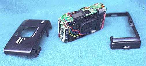
Two years of subliminal planning during my daily commute resulted in a cerebral blueprint of the solution. I had two goals. (1) Eliminate the cable; (2) have the cameras appear unaltered when un-twinned. I'm happy to announce that I've successfully implemented my plan, and the unsightly cable is gone! The completed Twin is shown in figure 1.
When I first considered twinning cameras, I briefly considered purchasing one the German "Siamese" twin cameras but my stereo budget isn't large enough and besides, I really enjoy building things myself. My logical conclusion was to "twin" a pair of standard 35mm cameras. My desire to keep the camera's bulk and weight as close to the Realist as possible, eliminated the possibility of using SLRs. It appeared that a "Point & Shoot" was my best choice. While twinning an old pair of Olympus XA2s was a low cost, mature, successful method, it was just a bit too mature. I felt that if I twined a current production camera, and propagated instructions on how to duplicate my effort, then the availability of modern featured stereo equipment would expose more people to the joy of stereo photography. After all, the supply of XA2 cameras isn't going to last forever. Thus I decided to select the smallest, most recently introduced "Point & Shoot" with an electronic shutter.
My search didn't take long. Long a fan of Nikon equipment, the current production Nikon Lite-Touch looked like it would satisfy most of my requirements. It has a well rated 28mm f/3.5 triplet, electronic everything, built-in flash, and it is tiny. It has a panorama mode switch, but all it really does is drop shutters that mask the top and bottom of the already wide angle image.
I bought one camera, deciding to wait to purchase the second until I had verified my ability access and modify the necessary electronic circuits. My first obstacle was mechanical The camera's heavily torqued Phillips screws eluded my attempts to remove them. My workshop grade screwdrivers weren't going to do the trick. Fortunately, my local hobby shop had just what I needed; a superb quality, miniature Phillips screwdriver made by the German firm "Wiha" . It removed the camera back screws like they were embedded in butter.
Before you start, make sure that the battery is removed from the camera. If the flash is charged, you will receive a severe shock if you touch the right place within the camera. Trust me - I shocked myself twice before I started taking this precaution. Once the flash has been charged, the battery can be removed and you'll still receive a shock. I recommend removing the battery and waiting for several hours before disassembling the camera.
Figuring out which of the numerous screws to remove is an accomplishment that I'll pass along, and let you benefit from my experience. The Nikon Lite-Touch body is encased within two clamshell halves held by six screws . You must remove both the front and back clamshells. I'll list each screws location reference as viewed from the camera's back:
Remember or record each screw's origin, for they are of varying lengths. To do this, I drew a diagram of the camera's body onto a piece of cardboard and pushed the screws through anatomically placed holes in the cardboard, for safekeeping.
The top/back clamshell will still be held with little catches. Slightly tilt out and up the right side, and the center portion of the left side. Once both sides are free, the entire top shell is tilted up and will fall free. The front clamshell is carefully tilted out from the top. Be gentile, as it can catch on some wires. Once you have separated the camera into its three basic parts, the fun begins.
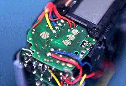
Still viewing from the camera's back, notice that you have exposed the shutter contacts. They are the gold plated printed circuit board circles on the top right side. They look sort of like circles of interlaced fingers. Refer to figures 2 and 3. There are three contact circles in a row near the front side of the top right. The center contact circle is the "shutter", and the contact circles on each side are duplicated "focus" contacts. Near these, to the right and toward the camera's back is another contact circle. This is the manual rewind button's contact. The focus contacts are duplicated due to the design of the shutter button. Pick up the plastic clamshell and take a look at it. The shutter release is a hollow rubber oval with three rubber posts on the underside. Look carefully and you'll notice that the outer two posts are longer than the center post. If you utilize an ohmmeter, you'll also discover that the posts are electrically conductive. When the shutter release button is pressed, the outer two posts will contact their associated interlaced contact circles before the center post. This is the half-way focus position. When the electrically conductive rubber post contacts the interlaced contact circle's fingers, it electrically shorts the fingers and fires the focus function. Continued downward pressure on the shutter button brings the center post into contact with its contact circle and fires the shutter.
![[twinfig2.gif]](twinfig2.gif)
Our objective is to connect wires to the "focus" and "shutter" contacts, as well as their electrical "common"; do the same to a second camera, and then connect the two together. You will need to use 30 gauge wire, as anything else is too large for the route it must take to the camera's base. Radio Shack sells 30 gauge wire, but they only seem to stock it with red insulation. You are less likely to make an error if you select a unique color for each wire. I didn't, however, instead marking each wire along its length with a magic marker code of one, two or three stripes. Cut 3 pieces of wire for each camera, each about a foot long
You cannot solder directly to the contact finger circles, as this would ruin the shutter button's functionality. You must follow the contact's printed board trace towards the left, and get out of the release button's path. This isn't entirely achievable, and you'll have to cut a small chunk out of the release button rubber edge, but it will still work fine (assuming you don't cut too large a chunk). You'll also need to scrape a small amount of the green solder mask from the trace, in order to obtain a large enough area for the solder to mechanically adhere the wire. This is delicate work and I recommend doing it under magnification.
Use as small a soldering iron as you can. Mine is an UNGARmatic soldering station designed for printed board work, and it was still too large to easily control. Tin the wire terminus and the prepared trace, apply a little solder flux to the wire, mate the two and briefly apply the iron to bond them. This is precarious work, and it was the only time that I was concerned that I'd damage the camera. However, I was overly concerned and the operation was completely successful. Just proceed slowly and carefully and you too will be successful. Once you've connected the three wires to the "focus", "shutter" and "common" contacts, as shown in figure 3, you are ready to prepare the baseplate electrical contacts for connection to the other end of the wires.
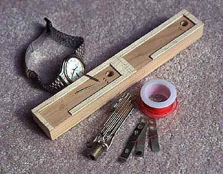
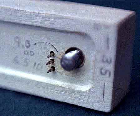
The material that I chose for the baseplate contacts was bronze foraged from military surplus phono-plug contacts. See figure 4. I disassembled a phono-plug and placed the bronze leaves into a vice. Then using a hacksaw, I cut out six eighth inch square contacts. A little sandpaper will smooth off the sharp edges.
Use a sharp knife, such as an Xacto, to cut a notch from the last tripod mount's support rib, as shown in figure 5. This provides a path for the wires.
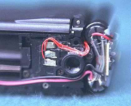
Group the three wires and route them to the tripod mount area of the camera base. You will need to tuck them behind the flash capacitor, as can bee seen in figure 5. As you bend and tuck the wires, tack them in place with a few drops of Duco cement.
Look at the base of the camera, next to the tripod mount. Test each bronze contact to make sure that it will fit into one of the little pockets formed by the tripod mount's support ribs. Using your soldering iron, tin the edge of each contact with solder. Now, trim and strip the end of each wire so that each will just reach one of the little pockets formed by the tripod mount's support ribs. Tin the ends of each wire, and then solder one of the bronze contacts to each wire, along the tinned edge of the contact. Epoxy a contact into three of the pockets, as shown in figure 5. Record which wire is connected to each contact, as the EXACT same order must be repeated in the second camera.
I originally planned to construct my new mount of cast structural plastic. To do so I fabricated a master of pine wood, creating the camera base pocket with a glued on 3/32 inch balsa plate cut with the aid of the template shown in figure 6. The completed, but un-painted, mount can be seen in figure 4. I filled the balsa to pine transitions with plastic wood and then painted the whole affair. Once this was accomplished, I found the painted base to structurally strong and sufficient to serve as the actual base. Therefore, I scrapped the cast plastic base idea.
Make two photocopies of the template in figure 6. Set the photocopy machine on "dark" so as to deposit a heavy layer of toner onto the paper. Place the toner side of one template against the balsa wood sheet, and place onto a flat surface. Next iron the template/balsa wood sandwich, with an ordinary clothes iron, to transfer the photocopy's toner to the balsa wood. Cut out the balsa pattern using a sharp knife. Iron the second template photocopy onto the pine wood mount to obtain the hole locations for subsequent drilling.
Glue the balsa pattern onto the pine mount using carpenter's glue. Once the glue has set, using a 1/4 inch drill bit, preferably in a drill press, drill the tripod mount holes. See figure 7. Using a 1/16 inch drill bit, drill the electrical plunger contact holes through the wooden mount. The holes should be a snug fit for the electrical plungers, so alter the drill size accordingly.
Time for another scary part. Take the camera body part that contains the tripod mount hole, and place it into one of the pockets formed by the balsa wood. Holding the camera body part firmly, use the electrical plunger contact holes in the mount as a template for drilling mating holes in the camera body part. If you have done everything right, either camera should be able to be placed into either balsa wood pocket and still have the electrical plunger contact holes align. This is an area for great care and precision.
Place the mount with the balsa side down, and using a router, cut two 1/8 inch deep pockets into the mount's bottom, such that each camera's electrical plunger contact holes emerge into a pocket. Then, using the router, cut a 1/8 inch deep channel between the two pockets. The pockets and channel will house the mount's wiring.
The base has three spring loaded electrical plungers, for each camera, to establish electrical continuity with the bronze contacts when the cameras are mounted upon the mount. Spring loaded plungers were utilized so as to provide a good electrical connection while simultaneously reducing some of the assembly precision. The necessary plungers are easy to obtain. I simply went to a local department store's watch department and asked for six identical watchband retainers. They should be free, as these are removed from customer's watches when new bands are attached, and most stores have an accumulation of the old retainers. The retainers that I chose were plated brass, which would be easier to solder than stainless steel retainers. Fortunately, the plated brass retainers outnumber the stainless ones. Tin one end of each plunger contact with solder.
Insert the plungers into the mount from the bottom, making sure that the top end of each plunger is at the same height, and extending slightly above the highest point in the mount's top. Now measure, cut and solder wire from each plunger contact to its positional mate on the other end of the mount. Tuck the wires neatly into the channel and pockets, and then fill the channel and both pockets with epoxy. This will retain the plunger contact and wires.
Fill in the balsa to pine transitions with plastic wood and then paint the entire mount in your preferred color. Be careful not to paint the electrical contact plungers.
The bottom of the Lite-Touch has a protruding base that made it very easy to assure perfect alignment when mounted in the pockets created by the balsa wood template. Each camera perfectly nestles into its cavity and is secured with a bolt through the wood, into its respective tripod mount. The main body of the camera clears the cavity's lip, thus they can stay on the mount during film loading/unloading. About the only time that they must come off the mount is to change batteries.
Synchronization between the two shutters, is excellent as long as both batteries are equally fresh. I've had no problem freezing waterfall droplets in perfect synchronization. Initial tests validate my calculations that the nearest object should be no closer than nine feet. The formula that I used was published by David Kuntz in the ISU STEREOSCOPY number 12:
               i * b
        n  =  -------
                 p
where:
	i = focal length, in mm
	b = baseline, in feet
	p = parallax (1.2mm for infinity far point)
	n = near point, in feet
Thus for the Lite-Touch mounted with a slight access gap between the cameras:
	28mm * .3775 ft
	--------------- = 8.808 feet (near point)
	    1.2 mm